Lab 07 - Sensors fusion: robot localization
Robotics II
Poznan University of Technology, Institute of Robotics and Machine Intelligence

Laboratory 7: Sensor fusion - robot localization
Back to the course table of contents
1. IMU (Inertial Measurement Unit)
An inertial measurement unit (IMU) is a sensor that can measure linear acceleration and angular velocity in 3D space and typically has 6 DoF (Degrees of Freedom). The IMU message is available in ROS sensor_msgs and fields definitions are shown below.
# This is a message to hold data from an IMU (Inertial Measurement Unit)
#
# Accelerations should be in m/s^2 (not in g's), and rotational velocity should be in rad/sec
#
# If the covariance of the measurement is known, it should be filled in (if all you know is the
# variance of each measurement, e.g. from the datasheet, just put those along the diagonal)
# A covariance matrix of all zeros will be interpreted as "covariance unknown", and use the
# data a covariance will have to be assumed or gotten from some other source
#
# If you have no estimate for one of the data elements (e.g. your IMU doesn't produce an orientation
# estimate), please set element 0 of the associated covariance matrix to -1
# If you are interpreting this message, please check for a value of -1 in the first element of each
# covariance matrix, and disregard the associated estimate.

Header header

geometry_msgs/Quaternion orientation
float64[9] orientation_covariance # Row major about x, y, z axes

geometry_msgs/Vector3 angular_velocity
float64[9] angular_velocity_covariance # Row major about x, y, z axes

geometry_msgs/Vector3 linear_acceleration
float64[9] linear_acceleration_covariance # Row major x, y z
2. GPS
GPS sensor has its origin in Global Positioning System. However, nowadays GPS sensors take advantage of several satellite systems such as GLONASS, Galileo, Beidou, or GPS. The sensor needs at least 3 satellites for 2D and 4 for 3D navigation. Typically, GPS tracks many more. The ROS message for GPS is available in sensor_msgs as NavSatFix Message. Definitions of fields are also shown below.
# Navigation Satellite fix for any Global Navigation Satellite System
#
# Specified using the WGS 84 reference ellipsoid

# header.stamp specifies the ROS time for this measurement (the
#        corresponding satellite time may be reported using the
#        sensor_msgs/TimeReference message).
#
# header.frame_id is the frame of reference reported by the satellite
#        receiver, usually the location of the antenna.  This is a
#        Euclidean frame relative to the vehicle, not a reference
#        ellipsoid.
Header header

# satellite fix status information
NavSatStatus status

# Latitude [degrees]. Positive is north of the equator; negative is south.
float64 latitude

# Longitude [degrees]. Positive is east of prime meridian; negative is west.
float64 longitude

# Altitude [m]. Positive is above the WGS 84 ellipsoid
# (quiet NaN if no altitude is available).
float64 altitude

# Position covariance [m^2] defined relative to a tangential plane
# through the reported position. The components are East, North, and
# Up (ENU), in row-major order.
#
# Beware: this coordinate system exhibits singularities at the poles.

float64[9] position_covariance

# If the covariance of the fix is known, fill it in completely. If the
# GPS receiver provides the variance of each measurement, put them
# along the diagonal. If only Dilution of Precision is available,
# estimate an approximate covariance from that.

uint8 COVARIANCE_TYPE_UNKNOWN = 0
uint8 COVARIANCE_TYPE_APPROXIMATED = 1
uint8 COVARIANCE_TYPE_DIAGONAL_KNOWN = 2
uint8 COVARIANCE_TYPE_KNOWN = 3

uint8 position_covariance_type
3. Odometry
Odometry is a term that utilizes data from motion sensors to estimate a change in position over time. The message is in ROS nav_msgs package. Below is presented raw message definition.
# This represents an estimate of a position and velocity in free space.
# The pose in this message should be specified in the coordinate frame given by header.frame_id.
# The twist in this message should be specified in the coordinate frame given by the child_frame_id
Header header
string child_frame_id
geometry_msgs/PoseWithCovariance pose
geometry_msgs/TwistWithCovariance twist
4. Kalman Filter
Kalman filter is a state estimator which uses a series of measurements observed over time to provide a more accurate estimation than those based only on a single measurement. In the Robot Localization package, the extended Kalman filter (EKF) is used. It is a nonlinear version of the Kalman filter utilized to estimate the state of nonlinear systems by linearizing them.
5. Robot Localization package
The Robot Localization is a ROS package which provides a collection of state estimation nodes. It allows using both EKF and UKF. Fusing sensor (odometry, IMU, GPS) and pose estimate (pose, twist) data. Integration of 15 states: - Position: x, y, z - Orientation: yaw, pitch, roll - Linear Velocity: x’, y’, z’ - Angular Velocity: yaw’, pitch’, roll’ - Linear Acceleration: x”, y”, z” Moreover, estimation is continuous also during the absence of continuous data.

6. Tasks
Download single_lap_processed.bag rosbag file shared by Edinburgh University Formula Student Team.
Run the
rostopic listcommand and check available ROS topics. Note the names of topics connected with odometry, IMU, and GPS sensors.In script
robot_localization_message_converter.pyfromfsds_roboticsIIpackage set input (published by rosbag) and output (available inrobot_localization_config.yaml, for GPS use/gps) topics names.According to the
robot_localizationpackage documentation and sections Operating in 2D? and Fusing Unmeasured Variables of this instruction, settruefor all utilized configurations inodom0_configandimu0_configinrobot_localization_config.yaml.Run the
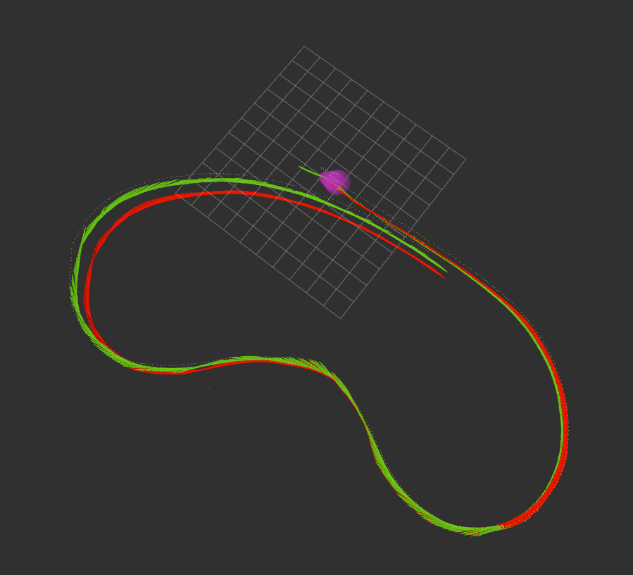
sensor_fusion_robot_localization.launchfile, in the other terminal playsingle_lap_processed.bagrosbag and check how the state estimation is visualized in Rviz.Write your own ROS subscriber for odometry data (
odometryandodometry/filtered). Save in separate files pose data in the format:timestamp tx ty tz qx qy qz qw, one per row.Using the
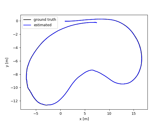
evaluate_ate.pyscript which is described here calculate Absolute Trajectory Error (ATE) between trajectories. In order to do:
- download associate.py and evaluate_ate.py scripts
- check association of timestamps of two data files (use
--max_differenceoption)
python associate.py odometry.txt odometry_filtered.txt- calculate ATE (also with
--max_differenceoption)
python evaluate_ate.py odometry.txt odometry_filtered.txt --plot xy_plot.png --verbose --max_difference <maximally allowed time difference for matching entries>- Add to the eKursy platform:
- screenshot from Rviz with full odometry visualization for
single_lap_processed.bag, - ROS subscriber script for odometry data (from task 6)
- text file with:
- used topics names (from rosbag)
- created
odom0_config, andimu0_configmatrices with descriptions of used state variables - Absolute Trajectory Error calculated for
odometryandodometry/filtereddata:
absolute_translational_error.rmse X m absolute_translational_error.mean X m absolute_translational_error.median X m absolute_translational_error.std X m absolute_translational_error.min X m absolute_translational_error.max X m - graph generated by the
evaluate_ate.pyscript
